
Understanding your garage door sensor wiring diagram is crucial for troubleshooting and DIY repairs. A wiring diagram provides a clear roadmap of your garage door sensor’s electrical connections, showing how each component interacts. This knowledge is vital not only for solving issues when your garage door fails to operate correctly but also for performing safe and effective maintenance.
Whether you’re facing sensor malfunctions or planning to upgrade your garage system, being able to interpret the wiring diagram can save time and avoid unnecessary expenses. This post will guide you through reading and creating a basic garage door sensor wiring diagram, empowering you to handle your garage door issues with confidence.
Why You Need a Wiring Diagram for Your Garage Door Sensors
Garage door sensors are critical components that enhance both the safety and functionality of your garage door system:
- Safety Mechanisms: These sensors prevent the garage door from closing if an obstruction, such as a person, pet, or object, is detected. This feature is essential for preventing injuries and damage.
- Operational Functionality: Sensors ensure that the garage door operates smoothly, opening and closing as expected without any unexpected malfunctions.
Having access to a garage door sensor wiring diagram is crucial for several reasons:
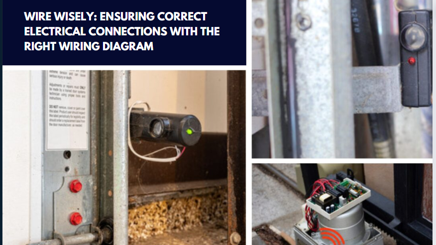
- Correct Electrical Connections: A wiring diagram helps ensure that all electrical connections are set up correctly, which is vital for the sensors to function properly.
- Troubleshooting and Maintenance: It allows for quick diagnostics and repairs if the garage door behaves erratically or stops working, pointing directly to issues that might be related to sensor wiring.
Common issues due to incorrect wiring include:
- Failure to Detect Obstructions: If sensors are not wired correctly, they may fail to detect obstructions, leading to potential accidents or damage.
- Communication Errors: Incorrectly connected sensors might not communicate properly with the garage door opener, causing it to malfunction—either not opening or closing properly.
Regular consultation of the garage door sensor wiring diagram can aid in accurately troubleshooting these issues, ensuring the garage door’s reliability and safety.
Components of a Garage Door Sensor Wiring Diagram
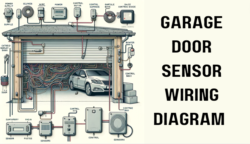
A garage door sensor wiring diagram includes several key components that are essential for the proper operation of your garage door. Understanding these components can help you effectively manage maintenance and troubleshoot issues. Here’s a breakdown of the main components typically found in a wiring diagram:
- Wires: These are the conductive elements that connect all the components of the garage door sensor system. They transmit electrical power and signals between the sensors, the power source, and the garage door opener.
- Terminals: Terminals are the connection points where wires are attached to components. They ensure that electrical connections are secure and facilitate the easy assembly or disassembly of connections for repairs or adjustments.
- Power Source: This supplies the necessary electrical power to the system. In most garage door sensors, the power source is typically a low-voltage transformer that is either part of the garage door opener or installed separately.
- Sensors: The sensors are the critical components that detect if there is an obstacle in the path of the closing garage door. There are usually two sensors located on either side of the garage door, near the floor. They need to be aligned properly and connected correctly according to the garage door sensor wiring diagram to function without error.
For clarity, each of these components can be represented by simple illustrations or icons within the wiring diagram. These visuals help in identifying each part on the diagram quickly, making it easier to follow along with the wiring setup or when conducting troubleshooting and repairs. Understanding your garage door sensor wiring diagram is crucial for ensuring that all parts are correctly configured and functioning as intended.
Step-by-Step Guide to Interpreting Your Garage Door Sensor Wiring Diagram
Understanding a garage door sensor wiring diagram can seem complex at first, but with a clear step-by-step approach, you can learn to navigate this essential tool effectively. Here’s a detailed guide to help you interpret your wiring diagram accurately:
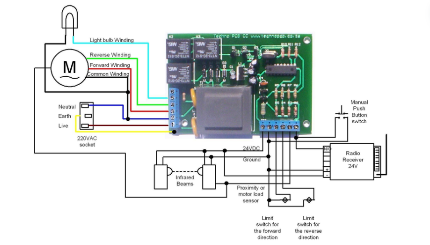
- Identify the Symbols: Begin by familiarizing yourself with the symbols used in the diagram. Typical symbols include lines (wires), circles (terminals), and squares or rectangles (power sources and sensors). Each symbol represents a different component of the garage door sensor system.
- Follow the Wires: Trace the wires from one component to the next. This will help you understand how power flows through the system and how the components are connected. Pay attention to the color coding of the wires if available, as this can provide additional information about their purpose.
- Check the Connections: Look at where the wires connect to the terminals. Ensure that each wire is connected to the correct terminal based on the diagram. Misconnections can lead to malfunctions or safety issues.
- Examine the Power Source: Locate the power source on the diagram. This is typically depicted as a large rectangle or a labeled icon. From here, you can see how power is distributed to the sensors and other parts of the system.
- Understand the Sensor Layout: Identify the positions of the sensors, which are usually found at the bottom of the garage door, one on each side. Ensure that the wiring to each sensor is correct and that there are no breaks or misrouting.
- Interpret the Grounding and Safety Features: Look for any grounding wires or additional safety features incorporated into the system. These are crucial for preventing electrical accidents and ensuring that the garage door operates safely.
Tips for Identifying Common Symbols and Connections:
- Solid Lines: Represent wires. The thickness and color might indicate different types or purposes of the wires.
- Dashed Lines: Often represent non-electrical connections, such as mechanical linkages or infrared alignment beams.
- Crossed Wires without a Junction: Indicate that the wires cross each other but are not connected.
- Crossed Wires with a Dot at the Intersection: Indicate a junction where the wires are electrically connected.
By taking the time to carefully study your garage door sensor wiring diagram and understand how each component interacts with the others, you can better troubleshoot issues, perform maintenance, and ensure the safety and functionality of your new garage door. Remember, a correctly followed wiring diagram is the foundation of a reliably functioning garage door sensor system.
How to Fix Common Wiring Issues
Handling common wiring issues in your garage door sensor system can be straightforward if you know what to look for and how to address them. Here’s a guide on identifying and resolving typical problems, with essential troubleshooting steps and safety tips.

Typical Wiring Problems and Solutions:
- Loose Connections:
- Symptom: Intermittent sensor function or no function.
- Solution: Check all terminal connections on the diagram to ensure they are tight and secure. Loose wires can lead to inconsistent sensor operations.
- Symptom: Intermittent sensor function or no function.
- Wire Corrosion:
- Symptom: Unreliable sensor responses or total failure.
- Solution: Inspect wires for any signs of corrosion or damage. Replace corroded wires and ensure the new connections are sealed against moisture.
- Symptom: Unreliable sensor responses or total failure.
- Incorrect Wiring:
- Symptom: Sensors not functioning as expected.
- Solution: Refer to the garage door sensor wiring diagram to verify each wire’s route and connection. Re-wire any incorrect connections according to the diagram.
- Symptom: Sensors not functioning as expected.
- Short Circuits:
- Symptom: Sensors or garage door opener behaving erratically.
- Solution: Inspect wires for fraying or contact with metal parts, which can cause short circuits. Replace damaged wires and ensure they are routed away from sharp edges.
- Symptom: Sensors or garage door opener behaving erratically.
Troubleshooting Steps:
- Disconnect Power:
- Always turn off the power to the system at the circuit breaker before attempting any repairs to avoid electrical shock.
- Always turn off the power to the system at the circuit breaker before attempting any repairs to avoid electrical shock.
- Visual Inspection:
- Examine the visible parts of the wiring for any obvious signs of wear, damage, or incorrect connections.
- Examine the visible parts of the wiring for any obvious signs of wear, damage, or incorrect connections.
- Test Connections:
- Use a multimeter to test the continuity of wires and the functionality of connections. This tool can help you pinpoint where breaks or faults are occurring in the wiring.
- Use a multimeter to test the continuity of wires and the functionality of connections. This tool can help you pinpoint where breaks or faults are occurring in the wiring.
- Follow the Diagram:
- Always have a copy of the garage door sensor wiring diagram at hand. This will be your guide in making sure that each component is properly connected and functioning.
- Always have a copy of the garage door sensor wiring diagram at hand. This will be your guide in making sure that each component is properly connected and functioning.
Safety Tips:
- Use Appropriate Tools: Ensure you are using insulated tools when working on electrical components to prevent accidents.
- Wear Protective Gear: Safety glasses and gloves are recommended to protect against sparks or sharp wire ends.
- Double-Check Your Work: After making repairs, review your work to ensure all connections are secure and correct according to the wiring diagram.
By systematically addressing common wiring issues using the garage door sensor wiring diagram as your guide, you can maintain the functionality and safety of your garage door sensors effectively. Remember, if you encounter complex issues or feel unsure about performing any repairs, it’s advisable to contact professionals like Veterans Garage Door to ensure your garage system is serviced safely and correctly.
Frequently Asked Questions
- What do the different colors on the wiring diagram mean?
The colors on a garage door sensor wiring diagram are used to indicate the purpose of each wire. Typically, black or red wires are used for power connections, white or green for grounding, and blue or yellow for signal connections. Always refer to the specific legend on your diagram, as color coding can vary.
- How can I tell if my garage door sensor is malfunctioning due to a wiring issue?
Symptoms of a wiring issue include the garage door reversing unexpectedly, failing to close, or the sensor lights blinking. To confirm a wiring problem, check the connections and alignment as depicted in your garage door sensor wiring diagram, and use a multimeter to test for continuity and proper voltage.
- What tools do I need to work on my garage door sensor wiring?
Essential tools include a screwdriver, wire strippers, a multimeter for testing electrical connections, and sometimes pliers. Ensure your tools have insulated handles to provide extra safety against electrical shocks.
- Can I rewire my garage door sensors myself, or should I call a professional?
If you have basic electrical knowledge and can follow the garage door sensor wiring diagram accurately, you may be able to handle minor wiring tasks yourself. However, for extensive rewiring or if you’re unsure about the process, it’s safer to call a professional. Technicians like those from Veterans Garage Door have the expertise to ensure that your system is correctly and safely wired.
5. What are the risks of incorrect wiring in garage door sensors?
Incorrect wiring can lead to malfunctioning sensors, which may not stop the garage door from closing on obstacles, posing a safety risk. Additionally, improper wiring can cause electrical shorts, potentially damaging the entire garage door system. Always ensure wiring is done correctly as per the garage door sensor wiring diagram to avoid these risks.
Conclusion
Understanding your garage door sensor wiring diagram is essential for both maintaining and troubleshooting your garage door system effectively. This knowledge not only helps in identifying and resolving issues quickly but also ensures that your garage operates safely and efficiently. Regular checks and familiarity with the wiring diagram can prevent many common problems and extend the life of your garage door.
However, if you encounter complex wiring issues or if you’re unsure about handling garage door repairs and adjustments yourself, it’s important to seek professional help. For residents in Citrus, Manatee, Sumter, Sarasota, and Lake County, Veterans Garage Door is your trusted source for comprehensive garage door services. Their expertise ensures that any issue, whether it’s a minor wiring fix or a major functional overhaul, is addressed safely and effectively. Trust Veterans Garage Door to keep your garage door system in optimal condition, providing peace of mind and security for your home.


